How to optimize laser parameters for better cleaning results?
Many operators assume that increasing laser power automatically improves cleaning performance. In reality, improper parameter configuration can reduce efficiency, cause incomplete removal, overheat the substrate, create discoloration, or waste energy. Laser cleaning is not simply about “maximum wattage”—it is about precise control of fluence, pulse duration, repetition rate, scanning speed, and beam overlap. Without systematic optimization, even a high-quality laser cleaning machine cannot deliver consistent industrial results.
Optimizing laser parameters for better cleaning results requires balancing pulse energy, frequency, scan speed, spot size, and overlap to ensure that the energy density exceeds the contamination ablation threshold while remaining below the substrate damage threshold. The correct combination depends on material type, contamination thickness, reflectivity, thermal conductivity, and desired surface finish.
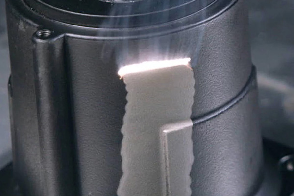
Laser cleaning performance is governed by photothermal and photomechanical principles. To optimize results, we must analyze energy density, pulse interaction time, thermal diffusion, and dynamic scanning behavior.
Table of Content
HIDE
Understanding the Core Optimization Principle: Energy Density (Fluence)
The most critical parameter in laser cleaning is fluence (J/cm²).
Fluence determines whether the contaminant is:
- Not affected
- Partially removed
- Completely ablated
- Or over-burned
Fluence Formula
Fluence = Pulse Energy / Spot Area
If fluence is too low:
- Contamination remains
- Cleaning is inefficient
If fluence is too high:
- Substrate heating increases
- Surface discoloration may occur
- Energy waste increases
Typical Ablation Thresholds
| Material | Approximate Ablation Threshold (J/cm²) |
|---|---|
| Light Rust | 0.2–0.6 |
| Thick Rust | 0.6–1.2 |
| Thin Paint | 0.5–1.0 |
| Bare Steel | 1.0–2.5 |
Optimal cleaning requires operating between contaminant threshold and substrate threshold.
Pulse Energy Optimization
Pulse energy (measured in mJ) determines the intensity of each laser burst.
Guidelines
- Thin contamination → Lower pulse energy
- Thick rust or epoxy → Higher pulse energy
- Delicate substrate → Moderate energy
Typical Industrial Ranges
| Laser Power | Pulse Energy Range |
|---|---|
| 500W | 1–5 mJ |
| 1000W | 5–15 mJ |
| 1500W+ | 10–20 mJ |
Higher pulse energy increases ablation force but also increases substrate heating risk.
Frequency Adjustment
Pulse frequency (kHz) controls how often energy is delivered.
Low Frequency
- Higher peak energy per pulse
- Strong ablation effect
- Suitable for thick rust
High Frequency
- Smoother cleaning
- Lower peak intensity
- Better for thin coatings
Example
| Frequency | Effect |
|---|---|
| 20–50 kHz | Aggressive removal |
| 50–150 kHz | Balanced cleaning |
| 150–300 kHz | Fine finishing |
Balancing frequency prevents overheating.
Scan Speed Optimization
Scan speed determines how long the laser interacts with a given area.
Slow Scan Speed
- Higher energy accumulation
- Risk of discoloration
- Deeper cleaning
Fast Scan Speed
- Reduced heat buildup
- May require multiple passes
Typical Industrial Scan Speeds
| Application | Scan Speed |
|---|---|
| Light Rust | 2000–4000 mm/s |
| Thick Rust | 1000–2500 mm/s |
| Paint Removal | 1500–3000 mm/s |
Optimization requires matching scan speed to pulse energy.
Spot Size and Focus Adjustment
Spot size directly influences fluence.
Smaller spot:
- Higher energy density
- Stronger cleaning
- Risk of overheating
Larger spot:
- Lower energy density
- Smoother surface
- Less aggressive removal
Adjusting focal distance allows controlled energy distribution.
Overlap and Scanning Pattern Control
Beam overlap affects uniformity.
Low Overlap
- Faster coverage
- Risk of uncleaned stripes
High Overlap
- Uniform cleaning
- Increased heat accumulation
Recommended Overlap Range
| Application | Overlap Percentage |
|---|---|
| Light Cleaning | 50–60% |
| Heavy Rust | 60–80% |
Optimized overlap ensures consistent results.
Substrate-Specific Parameter Strategies
Different metals require different settings.
Mild Steel
- Moderate pulse energy
- Medium frequency
- Balanced scan speed
Aluminum
- Lower pulse energy
- Higher frequency
- Faster scan speed
Stainless Steel
- Careful heat control
- Avoid discoloration
Multi-Pass vs Single-Pass Strategy
For thick contamination:
- Use moderate energy
- Apply multiple passes
Benefits:
- Better heat control
- Reduced substrate stress
- Improved surface quality
Optimization Matrix
| Parameter | Too Low | Optimal | Too High |
|---|---|---|---|
| Pulse Energy | Incomplete removal | Efficient ablation | Surface damage |
| Frequency | Rough finish | Smooth removal | Reduced peak power |
| Scan Speed | Overheating | Balanced cleaning | Residue remains |
| Spot Size | Weak cleaning | Targeted control | Excess heating |
Temperature Monitoring and Heat Control
Infrared thermometers or thermal cameras help ensure:
- Surface temperature remains below 150–200°C
- No heat-affected zone forms
- No warping occurs
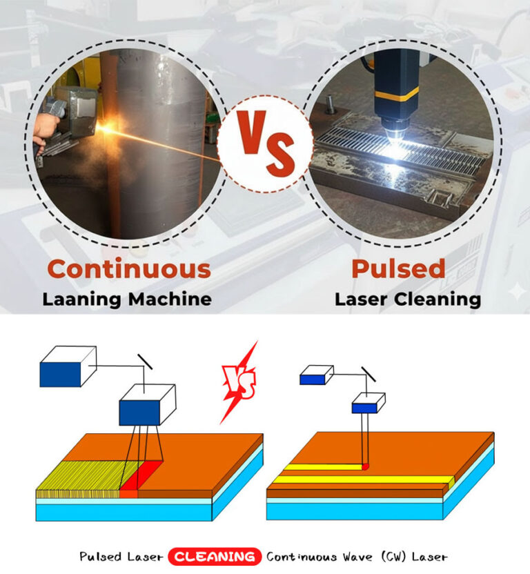
Pulsed systems naturally reduce thermal accumulation.
Productivity Optimization
Parameter optimization improves:
- Cleaning speed
- Energy efficiency
- Surface uniformity
- Reduced rework
Proper tuning may increase cleaning speed by 30–50%.
Common Optimization Mistakes
- Using maximum power unnecessarily
- Ignoring frequency adjustment
- Running too slow scan speed
- Not adjusting focal length
- Failing to test small sample area
Systematic testing ensures ideal configuration.
Structured Optimization Procedure
- Identify contamination type and thickness
- Start with moderate pulse energy
- Adjust frequency for surface smoothness
- Optimize scan speed to avoid overheating
- Fine-tune spot size and overlap
- Validate results with surface inspection
This structured approach minimizes trial-and-error.
Automation and Preset Modes
Modern laser cleaning systems include:
- Pre-programmed modes
- Material presets
- Data logging
- Remote diagnostics
Preset libraries reduce operator variability.
Performance Validation Methods
To confirm optimization:
- Visual inspection
- Surface roughness measurement
- Adhesion testing (for coating preparation)
- Metallographic analysis (if critical)
Repeatability ensures industrial reliability.
Energy Efficiency Considerations
Optimized parameters reduce:
- Electricity consumption
- Component wear
- Cooling load
- Operational cost
Efficiency improves long-term ROI.
Advanced Optimization: Pulse Shaping
Some high-end systems allow:
- Adjustable pulse width
- Variable waveform
- Energy ramping
Pulse shaping further improves selective ablation.
Final Technical Conclusion
Optimizing laser parameters for better cleaning results requires understanding the balance between energy density and material response. Pulse energy, frequency, scan speed, spot size, and overlap must be calibrated to exceed contamination thresholds while protecting the substrate. Increasing power alone does not improve performance; controlled parameter tuning ensures faster cleaning, better surface quality, reduced energy waste, and extended equipment lifespan.
Laser cleaning is a precision process governed by photonic physics and thermal management. With proper optimization, industrial users achieve maximum efficiency with minimal risk.
Let’s Fine-Tune Your Cleaning Performance
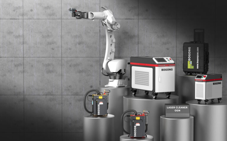
At BOGONG Machinery, we provide advanced pulsed fiber laser cleaning systems equipped with adjustable parameter controls and intelligent preset modes. Our engineering team assists customers in developing optimized parameter profiles tailored to their specific materials and contamination types.
If you want to improve cleaning speed, reduce substrate risk, or integrate laser cleaning into your production line, contact BOGONG Machinery. We’ll help you unlock the full performance potential of your laser cleaning system.
Talk to Bogong Laser Cleaning Machines ExpertsGet a Quote or Customized Solution for Your Application

-
Whatsapp: +86-15665870861
-
Email: info@bogongcnc.com